CNC machining has revolutionized the manufacturing industry, offering high precision and efficiency in producing a wide range of parts. As a seasoned supplier of CNC machining parts, I've encountered various defects during the production process. Understanding these common defects is crucial for both manufacturers and customers to ensure the quality of the final products. In this blog, I'll delve into some of the most prevalent issues in CNC machining parts and discuss their causes and potential solutions.
Surface Roughness
One of the most noticeable defects in CNC machining parts is surface roughness. This defect can affect the functionality and aesthetics of the part. Surface roughness can occur due to several factors, including tool wear, improper cutting parameters, and material properties.
Tool wear is a common cause of surface roughness. As the cutting tool is used over time, its edges become dull, resulting in a less smooth cut. This can lead to a rough surface finish on the machined part. To mitigate this issue, it's essential to regularly monitor the condition of the cutting tools and replace them when necessary.
Improper cutting parameters, such as feed rate, spindle speed, and depth of cut, can also contribute to surface roughness. If the feed rate is too high, the tool may not have enough time to remove the material smoothly, resulting in a rough surface. Similarly, if the spindle speed is too low, the tool may rub against the material instead of cutting it, causing surface irregularities. Adjusting these parameters to the appropriate values for the specific material and tool being used can help improve the surface finish.
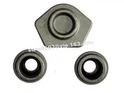
Material properties can also play a role in surface roughness. Some materials, such as cast iron and stainless steel, are more prone to producing a rough surface during machining. In these cases, using a different cutting tool or applying a surface treatment after machining may be necessary to achieve the desired surface finish. For example, our AA6061-T6 Aluminum CNC Machine is designed to handle aluminum materials effectively, reducing the risk of surface roughness.
Dimensional Deviation
Dimensional deviation refers to the difference between the actual dimensions of a machined part and its specified dimensions. This defect can occur due to errors in programming, tool deflection, thermal expansion, and fixture instability.
Errors in programming are a common cause of dimensional deviation. If the CNC program is not accurately written or contains incorrect values for the cutting parameters, the machined part may not meet the specified dimensions. To avoid this issue, it's crucial to double-check the programming before starting the machining process and use simulation software to verify the accuracy of the program.
Tool deflection can also lead to dimensional deviation. When the cutting tool is subjected to high cutting forces, it may bend or deflect, causing the actual cutting path to deviate from the programmed path. This can result in parts that are either larger or smaller than the specified dimensions. Using a stiffer cutting tool, reducing the cutting forces, or applying a tool compensation strategy can help minimize tool deflection.
Thermal expansion is another factor that can cause dimensional deviation. During the machining process, the cutting tool and the workpiece generate heat, which can cause the material to expand. This expansion can lead to changes in the dimensions of the part. To compensate for thermal expansion, it's important to monitor the temperature of the workpiece and the cutting tool and make appropriate adjustments to the cutting parameters.
Fixture instability can also contribute to dimensional deviation. If the workpiece is not properly secured in the fixture, it may move or vibrate during the machining process, resulting in inaccurate dimensions. Ensuring that the fixture is rigid and properly aligned can help prevent this issue. Our OEM Precise Tolerance CNC Machining Parts As Drawing are manufactured with high precision to minimize dimensional deviation.
Burrs and Chips
Burrs and chips are small pieces of material that are left behind on the surface of the machined part after the cutting process. These defects can affect the functionality and safety of the part and may require additional finishing operations to remove them.
Burrs are typically formed at the edges of the machined part when the cutting tool exits the material. They can be caused by factors such as improper tool geometry, high feed rates, and dull cutting tools. To reduce the formation of burrs, it's important to use a cutting tool with the appropriate geometry and to adjust the cutting parameters to minimize the cutting forces.
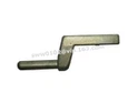
Chips are the small pieces of material that are removed from the workpiece during the cutting process. If the chips are not properly evacuated from the cutting area, they can accumulate and cause problems such as tool wear, surface roughness, and dimensional deviation. Using a chip breaker or a coolant system can help break up the chips and flush them away from the cutting area. Our Aluminum 6061-T6 Air Bung is designed to minimize the formation of burrs and chips during the machining process.
Cracks and Porosity
Cracks and porosity are defects that can occur in the material of the machined part. These defects can weaken the part and reduce its durability, making it more prone to failure.
Cracks can be caused by factors such as thermal stress, residual stress, and material defects. Thermal stress can occur during the machining process when the material is heated and cooled rapidly, causing it to expand and contract. This expansion and contraction can create internal stresses in the material, which can lead to the formation of cracks. Residual stress can also be introduced during the manufacturing process, such as during casting or forging, and can cause cracks to develop over time.
Porosity refers to the presence of small holes or voids in the material. Porosity can be caused by factors such as gas entrapment during the casting process, improper heat treatment, or the presence of impurities in the material. To detect cracks and porosity, non-destructive testing methods such as ultrasonic testing, X-ray inspection, or dye penetrant testing can be used. If cracks or porosity are detected, the part may need to be repaired or replaced.
Solutions and Quality Control
To minimize the occurrence of these common defects in CNC machining parts, it's important to implement a comprehensive quality control system. This system should include the following steps:


- Design Review: Before starting the machining process, review the design of the part to ensure that it is suitable for CNC machining and that the specified dimensions and tolerances are achievable.
- Material Selection: Choose the appropriate material for the part based on its intended application and the machining requirements. Consider factors such as strength, hardness, machinability, and cost.
- Programming and Simulation: Use advanced programming software to create accurate CNC programs and simulate the machining process to verify the accuracy of the program and identify any potential issues.
- Tool Selection and Maintenance: Select the appropriate cutting tools for the material and the machining operation and regularly maintain and replace the tools to ensure their optimal performance.
- Process Monitoring: Monitor the machining process in real-time to detect any deviations from the specified parameters and make adjustments as necessary. Use sensors and monitoring systems to measure variables such as cutting forces, temperature, and vibration.
- Inspection and Testing: Conduct thorough inspections and tests on the machined parts to ensure that they meet the specified dimensions, tolerances, and surface finish requirements. Use measuring instruments such as calipers, micrometers, and coordinate measuring machines (CMMs) to verify the accuracy of the parts.
By implementing these quality control measures, we can ensure that our CNC machining parts meet the highest standards of quality and reliability. As a trusted supplier of CNC machining parts, we are committed to providing our customers with high-quality products and excellent customer service. If you are in need of CNC machining parts, we invite you to contact us to discuss your specific requirements and explore the possibilities of working together.
Conclusion
In conclusion, understanding the common defects in CNC machining parts is essential for ensuring the quality and reliability of the final products. Surface roughness, dimensional deviation, burrs and chips, and cracks and porosity are some of the most prevalent issues in CNC machining. By identifying the causes of these defects and implementing appropriate solutions and quality control measures, we can minimize their occurrence and produce high-quality CNC machining parts.
If you have any questions or need further information about our CNC machining parts or our quality control processes, please don't hesitate to contact us. We look forward to the opportunity to work with you and provide you with the best possible solutions for your CNC machining needs.
References
- Groover, M. P. (2010). Fundamentals of Modern Manufacturing: Materials, Processes, and Systems. Wiley.
- Kalpakjian, S., & Schmid, S. R. (2013). Manufacturing Engineering and Technology. Pearson.
- Trent, E. M., & Wright, P. K. (2000). Metal Cutting. Butterworth-Heinemann.